 New
and Cool: Variable Refrigerant Flow Systems New
and Cool: Variable Refrigerant Flow Systems
Superior control and efficiency are
bringing VRF systems to America
by Sara Fernández Cendón
Summary: Variable
refrigerant flow (VRF) systems have been around for almost three
decades, but they’re new to the U.S. HVAC market. As American
engineers become familiar with the technology, and especially as
they learn of its energy efficiency advantages, more in the industry
might be willing to give the systems a try.
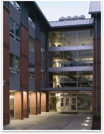
1: CITY MULTI VRFZ systems are installed on the roof of the Burlingham
Hall residence hall at Pacific University in Pacific Grove, Ore. Image
courtesy of Mitsubishi.
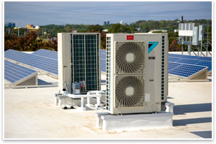
2: Daikin compressing units installed on the roof
of a building. Each of these can be connected to multiple evaporators inside
the building. Image courtesy of Daikin.
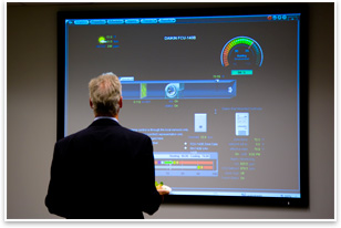
3: A central monitor that controls
the entire VRF system. Image courtesy of Daikin.
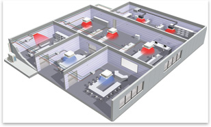
4: A heat recovery system
diagram.
Cooling the old-school way
If you’ve been shopping for HVAC systems lately, you might
have encountered a new contender among the usual choices. Introduced
in the U.S. about five years ago, VRF systems were invented in Japan
more than 20 years ago. They’re widely used not only in Asia,
but also in Europe and South America.
VRF systems manufacturers highlight qualities such as energy efficiency,
design flexibility for architects and engineers, quiet operation,
and the ability the system grants individual users to control temperature
in their own areas. Another appealing feature offered by most manufacturers
is a centralized monitoring application that gives users control
over the entire system from a single location or via the Web. The
technology that makes it all possible is sophisticated, but VRF systems
(also known as VRV, or variable refrigerant volume systems) are not
very complicated.
A quick review of air-conditioning principles might be useful in
describing VRF technology—the most basic principle, of course,
being that air conditioning removes heat from the space to be cooled
by pushing refrigerant through a cycle. The cycle comprises four
elements common to all HVAC systems, which is based on the fluid
dynamics that when a refrigerant expands, it becomes cooler; when
it is compressed, it becomes warmer; and changing phases from fluid
to gas or back again adds to the cooling/warming effect. So the system
is composed of a compressor, a condensing unit, a metering device
(or expansion valve), and an evaporator or heat sink.
In a direct expansion (DX) system, the simplest among air conditioning
systems, the “hot” part of the cycle starts at the compressor,
which compresses refrigerant vapor and turns it into a high-temperature
gas. The refrigerant then goes through a condensing unit, a series
of coils in which the gas loses heat and becomes liquid. The “cold” part
of the cycle begins as the liquid refrigerant passes through the
metering device, which causes a drop in pressure. The refrigerant
then goes through the evaporator (another series of coils), and in
the process of evaporating it absorbs heat from the surrounding area,
producing a cooling effect that is dissipated through fans. After
completing the cycle, the refrigerant goes back to the compressor
in its initial low-pressure, gaseous state.
Slight variations in the refrigerant cycle have led to different
applications designed for different uses. Window units, for example,
pack all the elements of the cycle into one small device—the
hot side being on the outside, the cool part facing the space to
be cooled. Split-system units split the hot side of the cycle (placed
outside the building) from the cold side (inside). In these types
of systems, cool air is often transferred from the evaporator to
many different rooms by an air-handling unit, which distributes the
conditioned air through a series of ducts.
Industry standards set limits on the length of piping running between
the condenser and the evaporator in DX systems. When the needs of
a particular project exceed such limits, chilled water systems are
often used as an alternative. In chilled water systems water is cooled
by a regular refrigeration system and then circulated through ducts
to air handlers throughout the building. Because there is no limit
to the permitted length of water pipes, these systems are often used
to cool large buildings or entire campuses. Chilling is often cycled
at night to take advantage of off-peak energy rates.
 The variable beauty of VRF technology The variable beauty of VRF technology
Configurations vary among the types of air-conditioning systems available,
but one key ratio remains the same: always one condensing unit
to one evaporator. For DX systems, this means that once a condensing
unit is connected to an evaporator inside the building, providing
cool air to several spaces requires either ductwork or additional
condensing units and evaporators.
Not so with VRF systems, in which one condensing unit can be connected
to multiple evaporators, each individually controllable by its user.
Similar to the more conventional ductless multi-split systems, which
can also connect one outdoor section to several evaporators, VRF
systems are different in one important respect—although multi-split
systems, like DX systems, turn on and off depending on whether the
room to be cooled is too warm or not warm enough, VRF systems constantly
modulate the amount of refrigerant being sent to each evaporator.
By operating at varying speeds, VRF units work only at the needed
rate, which is how they consume less energy than on/off systems,
even if they run more frequently.
Although systems vary among manufacturers, VRF technology is usually
available as heat pump or heat recovery units. Heat pumps provide
either heating or cooling. Heat recovery systems allow for simultaneous
heating and cooling—which means, for example, that one condensing
unit might be connected to six indoor units, three of which could
be used to cool some areas, and three of which could be used to heat
other areas, all at the same time.
The modular nature of VRF offers a dizzying array of options. And,
to help engineers interested in exploring the use of this technology,
the American Society of Heating,
Refrigerating and Air-Conditioning Engineers (ASHRAE) has assembled a group
to study VRF. ASHRAE included a description of the VRF system in
its 2008 handbook on HVC systems and equipment and is now working
on a separate chapter on VRF to be published in 2012.
Several manufacturers of VRF systems are part of the ASHRAE committee
working on documentation for the technology, but only a handful are
already marketing their systems in the U.S., with Mitsubishi
Electric HVAC Advanced Products Division in Suwanee,
Ga., and Daikin Industries (based in Osaka,
Japan, with U.S. headquarters in Dallas) currently being the major
players.
Both Mitsubishi and Daikin are taking steps to educate U.S. engineers,
architects, and contractors on the technology. According to Meredith
Emmerich, director of application support with Mitsubishi, about
10,000 people went through the company’s training on ductless
and VRF systems last year alone. The company offers support and training
through 1,100 locations across the U.S.
 Daikin’s Dallas location, too, includes a training facility
where VRF equipment is installed and exposed, so engineers, architects,
and contractors may come in and see the outdoor and indoor units,
the piping, the installation, and controls on all the models. Daikin’s Dallas location, too, includes a training facility
where VRF equipment is installed and exposed, so engineers, architects,
and contractors may come in and see the outdoor and indoor units,
the piping, the installation, and controls on all the models.
Breaking it down
VRF systems offer an energy-efficient solution that
provides considerable flexibility. But, as with any other HVAC system,
their cost-effectiveness and usefulness needs to be evaluated on
a building-by-building basis. VRF systems are a good option for buildings
with varying loads and different zones: structures such as hotels,
schools, and office buildings where individual users want to have
control over the temperature in their areas. VRF systems tend to
have greater piping length allowances than DX systems and use copper
piping with small diameters, which makes them suitable for buildings
with low-ceiling spaces or for adaptive reuse and other projects
aimed at preserving historic value with minimal destruction during
installation.
Less likely candidates to benefit from VRF technology are large
open volumes, such as gyms, theaters, or sanctuaries. These building
types often fail to maximize the potential of the system, which is
ideal for areas with different zones.
Lee Shadbolt, AIA, principal with Commonwealth
Architects, based in Richmond, Va., says his firm is considering a VRF system
for the renovation of Hotel John Marshall, a historic landmark built
in the 1920s. Energy efficiency was one of the main factors considered,
but there were other reasons to look at VRF.
“First, it’s a great application for multi-familiy residential
use,” he says. “Second, it was extremely efficient and
gave us a lot of points toward LEED certification. And third, it
allowed us to work with the high-rise nature of the building.”
Shadbolt says other options (such as split systems or a central
chiller boiler plant) have been considered for the project. But VRF,
which is about 20 percent more expensive than other alternatives
considered, is also significantly more efficient, according to his
team’s assessment.
 Regarding cost, Jami Billman, sales engineer with Daikin, says that
VRF systems can be designed both in expensive and more affordable
ways. For example, a system with one evaporator in every single room
may be more costly initially, but the installation might require
less ductwork. Or, in a different arrangement, several spaces might
share a nearby evaporator. The smaller footprint of VRF equipment
can also reduce costs. According to Billman, in most cases the system
eliminates the need to have mechanical rooms, so useable space is
given back to the client. Regarding cost, Jami Billman, sales engineer with Daikin, says that
VRF systems can be designed both in expensive and more affordable
ways. For example, a system with one evaporator in every single room
may be more costly initially, but the installation might require
less ductwork. Or, in a different arrangement, several spaces might
share a nearby evaporator. The smaller footprint of VRF equipment
can also reduce costs. According to Billman, in most cases the system
eliminates the need to have mechanical rooms, so useable space is
given back to the client.
Joe Bush, application specialist for City
Multi, Mitsubishi’s line of VRF systems, explains that Mitsubishi
is the only manufacturer to use two refrigerant lines, instead of
three, for heat recovery systems. He says this patented technology
translates into considerable installation cost savings as well.
Ramez Afify, PE, LEED-AP, director of engineering at New York-based
Clifford Dias Consulting Engineers, is a member of the ASHRAE group
devoted to the study of VRF. In general, he estimates the initial
cost of a VRF system to be 20 to 40 percent higher than a traditional
split/heat pump HVAC system, but, he says, operating costs might
be at least 10 percent less. According to Afify, the difference in
price between a VRF and a conventional system might be recovered
in fewer than five years.
Beyond the initial cost of VRF systems, disadvantages often cited
revolve around refrigerant lines and ventilation. Afify explains
that if VRF systems are large, as many chilled water systems are,
a significant amount of refrigerant gas, instead of water, ends up
running through the building.
“Of course refrigerant is not dangerous within certain volume
limits, but if the system grows huge, it becomes a concern,” he
says, adding that ASHRAE Standard 15, “Safety Code for Mechanical
Refrigeration,” discusses the topic in detail.
Concerning ventilation, Afify explains that providing outside air
can turn into a hurdle, because VRF units may require a separate
ventilation system, especially in hot and humid climates or when
dealing with high occupancy areas. Major manufacturers do generally
offer outside air processing solutions that can be tied into the
same control systems used for VRF units.
More than any of the above setbacks, however, Afify believes that
what has kept U.S. engineers away from VRF systems has been a lack
of familiarity and clear documentation. As more U.S. engineers become
familiar with the technology, many in the industry expect to see
VRF systems grow in popularity. |


