

08/2005
excerpted from Designing the Exterior Wall by Linda Brock, AIA
 The University of Washington’s
Meany Hall for the Performing Arts in Seattle was reclad with anchored
brick veneer in the early 1990s. The backup wall for the new veneer was
poured-in-place concrete, which reduced water-entry concerns. Existing
conditions, such as shelf angles located at different heights on various
elevations, presented particular design challenges in addition to the
technical problems.
The University of Washington’s
Meany Hall for the Performing Arts in Seattle was reclad with anchored
brick veneer in the early 1990s. The backup wall for the new veneer was
poured-in-place concrete, which reduced water-entry concerns. Existing
conditions, such as shelf angles located at different heights on various
elevations, presented particular design challenges in addition to the
technical problems.
The design team—Hewitt-Isley, architect; Russell Heliker and Linda Brock of Brock Associates, masonry consultant; and Phil Green, PE, masonry structural engineer—employed several strategies. First, the masonry consultant determined the minimum width and maximum spacing of expansion joints and, working with the architect, established a grid of vertical and horizontal expansion joints. As the shelf angles, and, hence, the horizontal expansion joints were typically spaced at 14-foot (4.26 m) intervals, the designers placed the vertical expansion joints at 14 feet on center to create 14-foot square panels. Using a subgrid of 7-foot (2.13 m) squares drew attention away from the areas where the shelf angles had been moved up half a foot from their typical location. There was also a desire to change the scale of the brutalist forms so the building would better relate to the campus architecture. The architect used the necessity of expansion joints as a mechanism to create a more human scale.
 Developing patterned grids
The architect then developed a variety of patterns, each relating to
the different forms of the building, and overlaid those on the expansion-joint
grid. Double, dark-colored “clipped header” brick in a
field of salmon-colored full-brick stretcher units served as staccato “dots” to
create lines or emphasize points. The design team developed three patterns
(which can be seen in the accompanying photograph).
Accenting the long expanses of veneer are horizontal bands of stacked pairs of dark clipped-header brick alternating in an intermittent sequence with similarly stacked pairs of lighter brick running across the building at 7-foot intervals. The dark-brick bands draw attention away from the drip edge of the terne-coated, stainless-steel flashing above and horizontal expansion joint below each shelf angle (which, in turn, runs along the middle of every other dark band). The joint beside every second dark brick above the shelf angle is void to provide full-height weep holes that essentially disappear beside the dark solid of the header.
After these bands turn the corner, they split at a diagonal, creating patterns reminiscent of the diaper or diamond patterns in the Flemish bond used on nearby campus buildings. Each diamond was contained within either a 7-foot square or, in the case of the tall, box-shaped fly gallery, a 14-foot square. A textured pattern of double, dark brick dots results from alternating a header and stretcher brick at the narrow vertical recesses where the vertical location of the shelf angles had to be staggered. (A vertical expansion joint was required in each location where shelf angles were discontinuous around a corner.)
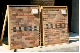
 The importance of on-site mockups
Using a single value and hue or color of brick for the field is very
difficult, as subtle variations are common and can be quite visible
in large fields of brick. To avoid these problems and create a more
uniform background, a selection of differing colored brick was specified.
Numerous mockups with simulated mortar joints were built on-site until
the desired mix was determined (as illustrated in the photograph).
Another visual problem occurs when a diamond pattern is created with high contrast brick, as an optical illusion often causes the diamonds to appear as if they were caving in along the diagonal lines. To avoid this phenomenon, the dark brick of the diagonal lines were not contiguous.
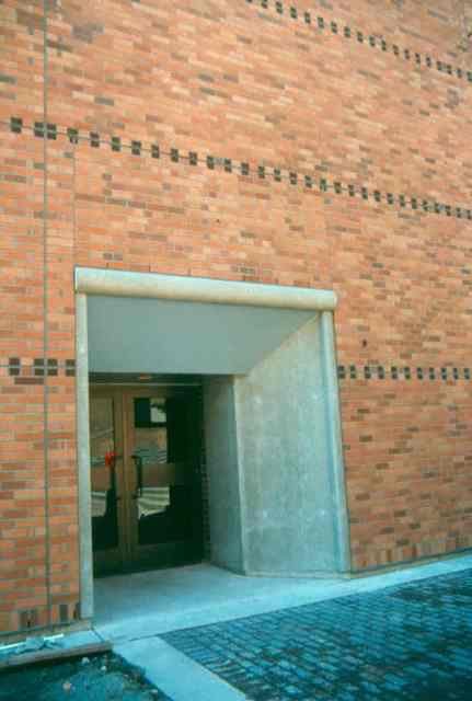
The team tackled existing conditions and aesthetics early
A number of existing conditions made this project difficult. An example
can be seen in the photograph of the exterior door opening. If this
had been new construction, the door could easily have been located
at the vertical expansion joint to the left. Instead, it fell 12 inches
(300 mm) to the side, necessitating a second expansion joint along
the jamb that carried through to the shelf angle above. (There is also
a third vertical joint that follows the right-side jamb to the underside
of the shelf angle.) However, this situation could just as easily arise
with new construction if the expansion joints are not located during
the preliminary design.
Because of the extensive upfront design efforts looking at durability in combination with the aesthetics of the new veneer, construction went smoothly and the project came in under budget, said University of Washington Project Manager Larry Nelson.
Copyright 2005 John Wiley & Sons, Inc. Reprinted with permission.
Copyright 2005 The American Institute of Architects.
All rights reserved. Home Page ![]()
![]()
 |
||
Designing
the Exterior Wall: An Architectural Guide to the Vertical Envelope, by Linda Brock, AIA, covers the gamut of types of walls and whole-wall
design for water, air, vapor, and thermal control and includes
ample details for brick, EIFS, concrete masonry, wood frame, and
curtain walls, with a strong emphasis on aesthetic enhancement.
For more information or to purchase the book ($67.50 AIA-members;
$75 retail) visit the AIA Store. Linda Brock is an associate professor directing the building technology program in the University of British Columbia, Vancouver, School of Architecture. Photographs © Linda Brock.
|
||